RANDOM PAGE
SITE SEARCH
LOG
IN
SIGN UP
HELP
To gain access to revision questions, please sign up and log in.
AS
A2
The Amplifier

|
- Increases the magnitude of the input signal.
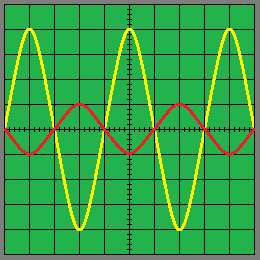
- It inverts the signal. (On an oscilloscope, the waves look upside down).
- In the oscilloscope trace here, the output (yellow) is four times bigger than the input (red). The gain is MINUS 4.
- MINUS because the signal is inverted and 4 because it's four times bigger.
|
Feedback
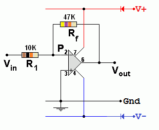
Feedback is the signal from the Op Amp output, fed back to the input, through Rf. The inverting amplifier uses negative feedback to control the gain.
The Circuit

- Gain = Vout / Vin
- Gain = - Rf / R1
- Vout / Vin = - Rf / R1
- In the example above, Gain = -47 / 10 = -4.7 It's OK to ignore the K because it cancels out.
- Rf and R1 control the GAIN. The formula has a minus sign in it because the amplifier inverts the input signal.
- The input resistance (impedance) of this circuit is equal to R1.
- The output is bigger than the input and inverted.
For the Falstad Circuit Simulation, CTRL+Click Inverting Amplifier Gain = -4.7
In options, check European Resistors and uncheck Conventional Current.
Alternatively view Inverting_Amplifier.txt.
Save or copy the text on the web page. Import the saved or copied text into the Falstad simulator.
Here is the new HTML5 Simulator Site.
Virtual Earth
Explanation: Operational amplifiers have a very large open loop gain. So if the output is a few volts, the inverting input voltage must be very small (a few microvolts). This voltage is so small, it is called a virtual earth.
The inverting input, labelled "P", is a Virtual Earth because the voltage here is approximately zero as long as the amplifier is not saturating or limiting.
For Maths Experts
Ohm's Law can be used to predict the gain of the Inverting Op Amp.
No current flows into or out of ideal Op Amp inputs. Therefore the current in Rf is equal to the current in R1. Using Ohm's law (V = I R) and since the voltage at P is zero ...
Vin = -I R1 so I = - Vin / R1
Vout = I Rf so I = Vout / Rf
- Vin / R1 = Vout / Rf
Gain = Vout / Vin = - Rf / R1
Measure the Gain of an Inverting Amplifier
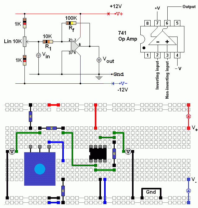
Build this inverting amplifier and measure the gain. The volt meters should be set to the 20 Volt range.
Plot a graph showing Vin on the X axis and Vout on the Y axis. The graph gradient gives you the gain.
Gain = -Rf / R1 = - 100/10 = -10.

reviseOmatic V3
Contacts, ©, Cookies, Data Protection and Disclaimers
Hosted at linode.com, London


